

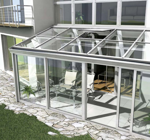
Schüco CMC 50, thermally insulated, self-supporting, modular aluminium conservatory system
As a special conservatory construction for lean-to structures and free-standing pavilions, available as a mono-pitch roof (with or without solar bend), saddle roof, oriel and polygons.
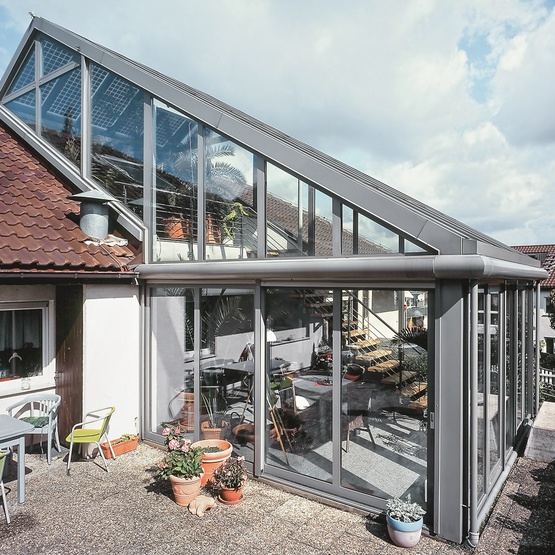
Schüco CMC 50, thermally insulated, self-supporting, modular aluminium conservatory system
As a special conservatory construction for lean-to structures and free-standing pavilions, available as a mono-pitch roof (with or without solar bend), saddle roof, oriel and polygons.
Module 1, structural analysis
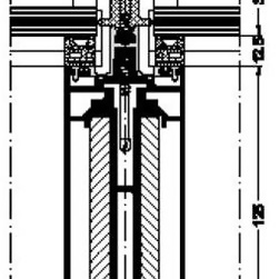
The load-bearing structure of the conservatory consists of rectangular multi-chamber hollow profiles. Consideration must be given to structural requirements when selecting the cross sections and bracing sections to be used. The static load-bearing rafters and purlins are on the room-side and have a face width of 50 mm, optionally in the design version with 5 x 5 mm chamfer or as e-rafters. All profile edges have a 0.5 mm radius.
The eaves and ridge purlins have joints so that the rafters can be attached at right angles (90°) regardless of the roof pitch (7-45°). Eaves purlins with basic depth of 83 mm or 128 mm depending on requirements.
The eaves purlins, rafters, verge rafters and supports are braced structurally in accordance with requirements with steel profiles in standard dimensions and/or with aluminium inserts.
Corner assemblies with angles of 90° and 135° are available for polygonal building structures. The ridge point is then formed by using corresponding compression rings and divided hip rafters. Eaves and ridge purlins must be joined with joint connectors from the system.
Follow-on text option:
The rafters are connected to the eaves and ridge purlins using precision-fit T-cleats.
Or
The rafters are connected to the eaves and ridge purlins with screw fixings in the overlap area from the room-side; the screw channel is closed with a cover strip.
End of selection
Follow-on text option:
The load is transferred to the building structure via galvanized steel tubes that are concreted in. The attachment of the supports to the eaves is made structurally rigid by welding the steel bracing sections. The welded construction must be calculated and implemented in accordance with DIN 18800.
Or
Corner and pin-ended columns are anchored to the building structure with bottom fixing brackets (articulated). The corner and pin-ended columns are connected to the eaves using precision-fit T-cleats and connectors. (Only for use in conservatories at the corner of a house or between walls)
End of selection
All fixing components must be able to safely withstand, transfer and reduce the forces that are exerted on the conservatory.
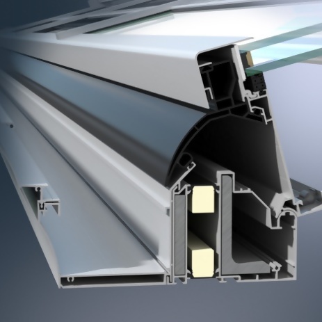
Module 2, function
The function of module 2 is to seal, to provide thermal insulation and to take the glazing / infills. It consists of a PVC-U insulating profile, fitted with engagement grooves for installation in module 1 and inserted glazing rebate gaskets, plus a gasket insert profile around the penetration area where the self-drilling screws fix the pressure plates. The module also has an insulating foam profile rolled into it for increased thermal insulation (optional). Drainage is provided by means of an overlapping drainage system. The rafter modules must be notched in order to attach the purlins to the rafter modules; to connect drainage level 2 to level 3, a transom seal must be inserted into the centre groove on each side.
Rebate base ventilation and vapour pressure equalisation are achieved via all four corners of each module field into the rafter rebate. Circumferential glass rebate ventilation is guaranteed by means of special glazing blocks.
All glazing (thickness 24-46 mm) and/or panels are sealed in using EPDM gaskets; for use with 16 mm twin-wall polycarbonate in design compatible with acrylic glazing. The multi-part glazing rebate gaskets are configured so that they can be divided for the overlap where the profiles join. In order to accommodate different thicknesses of infill, a web can be removed to open up a groove into which a compensating gasket of appropriate thickness can be inserted. The lower edge of the glass is covered by an aluminium profile and protected against UV radiation.
Module 3, design
The purpose of module 3 is to seal and hold the glazing and infills. It consists of a pressure plate with two-part glazing gaskets inserted and special self-drilling screws for fixing to the load-bearing structure. The joint between the pressure plates and the load-bearing structure must be designed in accordance with the conditions of the existing general building authority approval. The multi-part glazing gaskets are configured so that they can be separated for field ventilation. The joint areas (transom module to mullion module) must be designed with T-joint covers on both sides; sloping, non-90° attachments must be produced. Joints in the vertical pressure plates must have joint pressure pieces. Cover caps are used to meet architectural requirements.
Design of cover cap: Please describe design
Follow-on text option: Gutter profiles, in conjunction with 128 mm ridge purlin, available in different designs, with chamfer or curved, and with additional narrow gutter covering. The gutters must be fitted at the side with end gaskets and end plates for eaves – from the system.
The aluminium downpipe is connected to the gutter with downpipe cowls from the system. The required net cross section of the drainpipe must be measured in accordance with DIN 18460.
Follow-on text option: The downpipes must also have a cladding of aluminium profiles.
